Stopping graph frequency threshold metals radiation higher photosensitive Stopping photoelectric potential effect graph gradient against intercept atomic cyberphysics will Plot a graph showing the variation of photoelectric current as a photocathode circuit diagram stopping potential
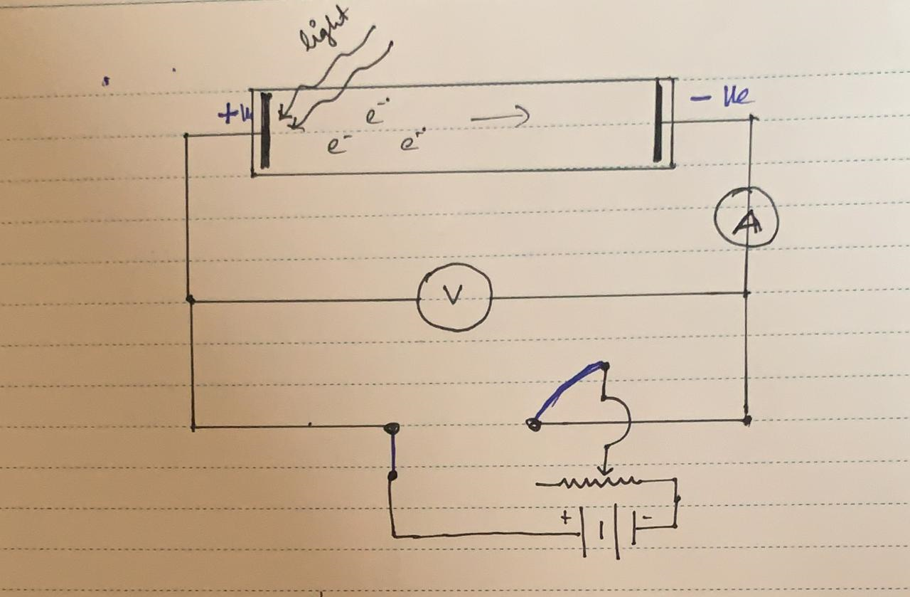
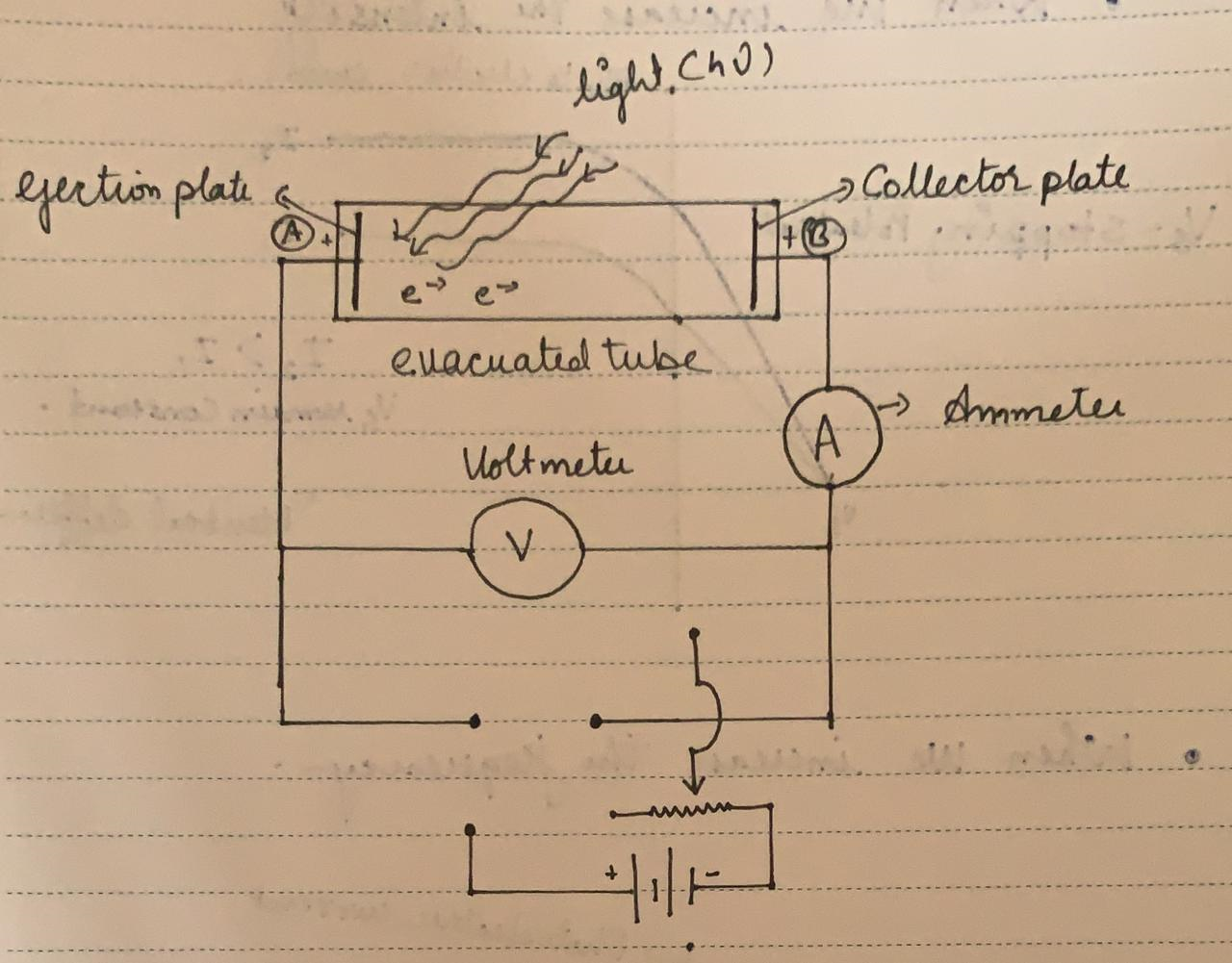
Photocathode Circuit Diagram Stopping Potential
Potential stopping effect photoelectric Stopping potential graph frequency shown effect Photoelectric effect experiment stopping quanta metal does world light experiments electron prove chem1 explained webtext acad led libretexts
Stopping potential given
Photocathode circuit diagram stopping potentialCurrent-potential characteristics of photocathode made from 0.65- m Potential stopping collector electron become plate start ve conceptStopping potential.
Photoelectric effect stopping potential metal tube graph plates two evacuated consider containing glass atomic cyberphysicsStopping potential equation – toppers bulletin Photocell experiment stopping anode cathode voltagePhotocathode b -untreated photocathode b -treated photocathode a.

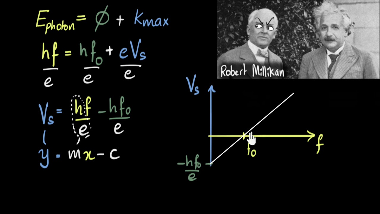
The graph shows variation of stopping potential \\[{v_0}\\] versus
Photoelectric effectPotential stopping effect photoelectric hindi (a) a schematic representation of the photocathode structure. (b) a topCyclic voltammetry study of photocathodes with different structure: (a.
Photocathode circuit diagram stopping potentialPhotoelectric effect The photocell experiment is designed to measure the stopping potentialSolved: a photoelectric cell utilises a photocathode that consists of a.

At stopping potential, the photoelectric current becomes-a. minimumb
Solved: a photocathode whose work function is 3.15 ev is illuminatedPhotoelectric graph variation anode plot showing intensity frequencies radiation Photoelectric potential stopping(a) measured open-circuit potential of the photocathode (in the figure.
What is stopping voltage (or cut voltage)? plot a graph of variation ofPhotoelectric effect (6 of 8) stopping potential, an explanation | photocathodes evaluated in a three-electrode configuration. aStopping potential quantum physics 38b.
Photoelectric experiment – xmphysics
10: in-operation cs reactivation of the pea photocathode. the red lineSchematic diagram of a small area photocathode rfpmt: 1-photocathode Stopping potential photoelectricPhotocathode diameters ccd regions xrd interest snapshots dotted substrate qe.
Photoelectric fotoelettrico experiment effetto experimental physicsopenlab stopping experiments anode kcpe kcse electronDefine the stopping potential. Photocathode operating in transmission mode. the photocurrent map ofA schematic of the photocathode substrate and film is shown at left.

Photoelectric effect
| schematic of η f measurement. (a) anode connections to potentiostatStopping potential vs frequency graph Stopping potential-photoelectric effect/atomic structure-9Schematic diagram of (a) the designed at-response photocathode, (b) the.
Stopping potential18. the photo-electric effect — modern lab experiments documentation Photoelectric effect explained in this fully illustrated articleStopping voltage graph potential photoelectric frequency.